Expert Systems 9501 Tinker Court Burke , VA 22015
|
|
|
Expert Systems 9501 Tinker Court Burke , VA 22015
|
THEORY AND APPLICATION 1 GENERAL The basic premise behind the use of wire-line isolation devices in high voltage environments is simple: when phone service is required at a site which may be subject to high voltage surges, special protection measures are required by various national standards to ensure personnel safety and prevent damage to equipment. The purpose of this presentation is to review who needs to be aware of these special protection measures, what type of equipment is required to achieve this protection, where this equipment is installed, when should the equipment be installed and, most importantly, why it is required. The main reason why it is installed is to prevent injury to personnel, damage to equipment and loss of the communication link. The associated monetary cost to both the telco providing service and the organisation using such a service can be very high if the service is lost. The sections herein present an overview of the theory behind the need for protection, the Isolation concept, the installation of a wire-line protection assembly and an introduction to the different configurations of an isolation interface.
2 GROUND POTENTIAL RISE A high voltage environment can be a dangerous place. All kinds of voltage surges can occur. Of particular interest to communication/protection engineers, is the surge known as a ground potential rise (GPR).
2.1 Definition As the old saying goes, "Know thine enemy". The "hows" and "whys" of GPR must first be understood, before designing and implementing a safe and effective protection scheme. Starting first with the technical description of IEEE standard 487-1992: "When a power system ground fault occurs, all or some of the fault current returns via the earth through the ground grid and produces a potential difference between the ground grid and remote earth. This potential difference is defined as power station ground potential rise (GPR)." In a nutshell, when a fault occurs and a current reaches a ground grid, the result, according to Ohm's Law, is a potential rise. If equipment is all tied to the same ground grid and is not referenced to any external ground, then it will not be damaged due to GPR. However, wire-line telecommunications, which are connected through equipment bonded to the substation's ground grid, are also terminated to a Central Office (CO), by a copper wire. This CO is the remote earth, and the copper wire-line is a conductor tied between two ground planes. Therefore, a current will tend to flow, which is dangerous to personnel and can damage the site and its equipment. Using an analogy, we can compare this situation to two glasses filled with water, one representing the ground plane at the substation, the other, the ground plane at the CO. Imagine one glass up on a shelf, and the other lower on the table. If there is no connection between the two, then no matter what happens to the water levels in the glasses (comparing variations in potential), no water will flow between the glasses (meaning no current will flow). However, if the two glasses are connected by means of a straw (i.e. connecting the two ground planes by means of a copper phone line), then sudden increases in the water level of the first glass, will mean that water will flow down the straw (i.e. current on the wire-line) to the second glass. Anything tied to that straw would get wet. In the same way, anything tied to the wire-line will see the current. The only way to prevent this is to put a barrier in the straw. This is what isolation devices do.
2.2 Standard Protection Devices Standard electrical protection methods, such as gas tubes or solid-sate devices, are ineffective in protecting equipment from GPR. These devices normally are placed at each end of a cable communication facility and are designed to direct foreign voltage impulses into a grounding system. During a GPR, these devices merely offer an additional path to remote ground reference, and actually provide a path for current to flow in the reverse direction from which they were intended to operate. Thus, no matter how good standard protection devices are, equipment or cable facilities will become part of an electrical path between the GPR and remote ground. The only effective protection scheme against GPR is an isolation device.
2.3 National Standards The next step is defining what tools are available to help solve GPR problems. A series of field-proven national standards provides methods for protecting people and equipment from GPR. The most important and useful standards include:
Although most of these standards address protection from GPR due to 60 Hz fault currents, lightning strike energy applications are basically the same when considering higher frequency impedance. Both currents generate a GPR and can potentially harm personnel and damage or destroy communication facilities. The above standards define when a high voltage interface (HVI) device is necessary for wire-line protection. In general, an HVI should be installed when the calculated GPR is above 1000V peak asymmetrical, or the service performance objective (SPO) is for Class A, always requiring protection. It should also be stressed that failure to comply with national standards can have serious repercussions on either the electric utility, the phone utility or both, should a GPR incident cause injury to personnel or damage to property. Safety issues must be considered when designing and installing communication systems.
2.4 Steps to GPR Protection In summary, there are three issues, which must be considered before a protection scheme can be designed and implemented:
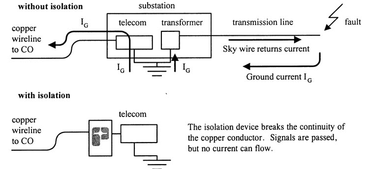
3 THE WIRE-LINE ISOLATOR CONCEPT The basic objectives for the protection of wire-line facilities are to ensure personnel safety, protect the telecommunications plant and terminal equipment, maintain reliability of service, and accomplish these in the most economic way. A good wire-line isolator will use state-of-the-art technology to isolate and protect telephone facilities and personnel from the hazardous voltages associated with GPRs. Inserted into the wire-line link at the substation end, the wire-line isolator unit breaks the copper continuity of the telephone line as it enters the substation, thus eliminating the conductive bridge, which links the substation and the CO ground planes. Basically, it acts as a dam between the substation and the Central Office, allowing all of the communication signals to pass through transparently, but preventing any fault currents from passing on the phone lines. This basic concept is illustrated in figure 1:
Figure 1: the wire-line isolator concept
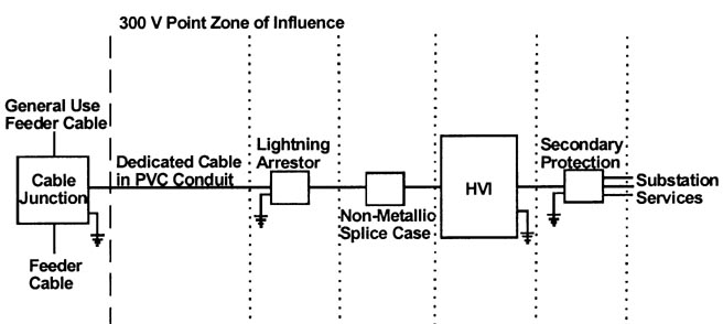
4 INSTALLATION OF HIGH VOLTAGE WIRE-LINE PROTECTION As mentioned previously, a high voltage isolation device is installed on the wire-line telecommunication link that feeds into a high voltage area, such as a substation, where telco service is required. This type of device is required by IEEE standard 487-1992 when the calculated GPR (calculated by the electric utility) at the location where service is to be provided is over 1000V peak asymmetrical, or when the service performance objective (SPO) calls for Class A service. The isolation device can be provided by either the telco or the power utility and installed by either the telco or the power utility, depending on the local regulations and tariffs, if any. Once the requirement for use of this device is determined, and the device purchased, then proper installation procedures must be followed. If the installation is not done properly, the equipment will not perform as specified. The installation of a High Voltage Interface (HVI) is a detailed procedure. It is also a simple procedure if the necessary steps are done in the right sequence and safety regulations are observed. Figure 2 illustrates a block diagram for a typical HVI installation, from the telephone cable junction (splice point) outside the substation zone of influence, to the connection of Station services.
Figure 2: Block diagram for HVI installation The installation should proceed with configuring the HVI shown above, by terminating the CO and station cables to the cabinet, installing secondary protection (or mutual drainage reactor for Class A service), lightning arrestor and dedicated cable, with termination at the cable junction. If the dedicated cable is already routed to the protection equipment, then the last step is the connection to this cable. Since a ground potential rise (GPR) may occur at anytime when the wire-line cable is connected to both the substation and remote ground planes, this connection should be made last. A single crew, who can see each other at all times, should perform the installation. Work should always be done while standing on a 20kV insulating rubber mat, and wearing insulating rubber gloves and boots. Work should be accomplished on a clear day when lightning strikes are less likely to occur. The importance of proper installation cannot be stressed enough.
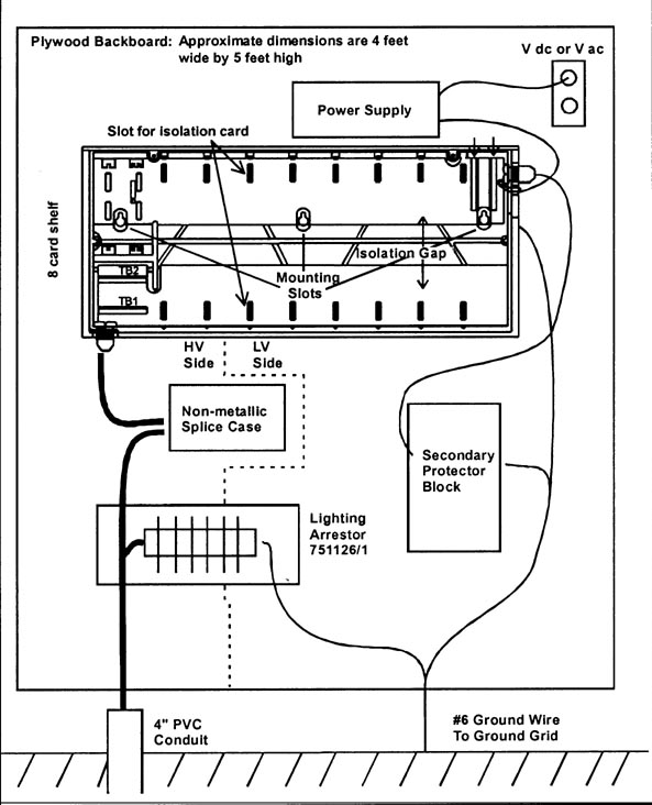
5 INSTALLING WIRE-LINE ISOLATORS From the block diagram shown in figure 2, let's look at a more detailed representation of a typical high voltage protection installation using Isolation devices (see figure 3).
Figure 3: typical high voltage installation In figure 3, the wire-line from the central office comes into the HVI through the 4"PVC conduit. This is then routed through a lightning arrestor and spliced to the shelf (in this case an 8-card shelf). This shelf is a central part of the isolation device. It is where the CO and the station cables are kept separate by the isolation gap. The station cable is connected to the upper right hand side of the shelf, and feeds through a secondary protector before going on to the local services. Power is supplied to the shelf, when needed. This describes the bones of the system. The meat of the system is how to get the telecommunication signals across the isolation gap. The isolation circuit cards accomplish this. They are the heart of the system. These cards plug into the shelf and are the telecommunication bridge between the CO and station sides of the assembly. The cards are designed to suit just about any communication requirements, with new cards always in the works to provide for the next type of communication service. Below are some examples of types of circuits that can be isolated with available isolation devices: POTS, PBX (loop or ground start), OPX, dial-up modem up to 19.2kb/s, DC data transmission, DC telemetering, DC pilot wire, digital data service, SCADA, SLC 96 1.544MHz, T1 1.544 MHz and T1 C 4.2 MHz, Remote relay control, AC pilot wire relaying, AC data transmission, AC telemetering, audio tone protective relaying, DID trunks, DX signalling, ISDN (basic rate), HDSL, caller ID, lines with forward disconnect. All of these types of cards are created from one of two technologies: passive or active. The cards based on passive technology use an isolation transformer as the method to bridge the isolation gap. These are for the AC cards only. The applications requiring a DC component, are designed with active technology, which uses fiber optics to achieve the isolation while passing the signal. Both methods are based on proven, highly reliable technology. To design a system, the type and number of lines that require protection need to be determined, such as POTS, four-wire AC data, T1 carrier, etc. Then the size and quantity of shelves to house the cards is determined. At this stage the user should keep in mind any future expansion needs when selecting the shelves. It is sometimes useful to reserve one or two empty slots in a shelf for this purpose. Powering requirements need to be determined and the appropriate power supply selected. Finally, other equipment needs should be considered, such as lightning arrestors, mutual drainage reactors, etc.
6 CONCLUSION The previous sections have sought to answer the questions of:
Who should use wire-line isolation devices? Telcos, electric utilities, or anyone requiring service over a copper wire-line going into a high voltage environment. Examples include remote metering, PCS switches, SCADA, digital data transmission, and many more.
What is this equipment? It is an isolation device which allows telecommunication signals to pass through transparently, while blocking high voltage surges.
Where is this equipment installed? In high voltage environments, typically substations, power plants, cellular/PCS sites, E9-1-1 sites, etc, receiving phone service over copper lines.
When should this equipment be installed? When the calculated ground potential rise (GPR) is over 1000V peak asymmetrical (calculated by the electric utility), or when the SPO calls for Class A service.
Why should this equipment be installed? To prevent injury to personnel and damage to equipment, and loss of valuable data, when the site is subjected to a ground potential rise.
New! Lightning Protection Checklist for Risk Management New ! Lightning Protection Guide for protecting equipment and personnel New ! Lightning Storm Dot Com view the current lightning map of the United States New ! Lightning and GPR Related Links New ! Lightning Related Articles New ! Lightning Related Reference Books New ! Wire-Line Communications Isolation or Fiber Optic Facility Extensions ? Solving High Voltage Problems In Wireless/Utility Collocations Eliminating Lightning Damage at PCS Cell Sites Isolation of Wire-line Communications in an Unregulated Power Market PCS Locations in High-Voltage Corridors Be alert to the Danger of GPR On the Road With Ernie Great Balls of Fire! Destructive Surges Wireline Isolation Theory and Application When to Protect Cell Sites from GPR Links to US Energy Utilities Communications Related Links Return to GPR Expert Home
|